Sanitary Pipe Fittings Autocad Jobs
Sanitary Pipe Fittings Autocad Jobs Rating: 4,2/5 3325votes
A typical plumbing fixture connects into an individual stack or riser. The oulet of the fixture trap connects to the side inlet of a sanitary tee. The bottom outlet of the sanitary tee drains, via an intermediate pipe, into a waste line. The top outlet connects, via intermediate piping, to a vent line or vent stack. Revit has two system classifications and types for sanitary systems--sanitary (waste) and vent.
When you got to draw the vent pipe, draw a small segment to remain 'sanitary', add a coupling and then draw the vent pipe. They should stay. A coupling does not isolate the vent system from the sanitary system. If you draw the vent. But, in this instance, Revit does not do a great job. If all you want to do. A $1.8 billion, privately-held company, Swagelok Company designs, manufactures, and delivers an expanding range of the highest quality fluid system products and solutions. Our end-to-end quality system—from sourcing, raw materials and tooling to continuous improvement and predictive maintenance—helps ensure the.
In the real world, vent systems and waste systems are connected at each fixture. However, Revit does not seem to recognize this fact. If you connect a fixture to the waste system, starting at the fixture, Revit will correctly assign the piping to the sanitary classification and system type. The easiest way to connect the fixture, in my experience, is to select the trap arm outlet, right click, and 'Draw pipe' to the main. This places an elbow between the trap arm and the drop to the main. Then, select the elbow, and convert it to a tee by clicking the top plus sign.
However, if you select the tee and 'draw pipe' from the top outlet of the tee, it will be assigned the sanitary system classification and type, not vent. You can select Pipe from the ribbon, set the system type to Vent, and draw the vent pipe from the top outlet of the tee. So far, so good. Sooner or later, however, Revit will change the vent piping you just drew to Sanitary. If you use filters to show the sanitary piping as solid lines, and vent piping as dashed lines, all of the vent piping will be rendered in solid lines. Similarly, if you use a pipe tag that includes the size and system abbreviation, all of the piping will be tagged as sanitary. The only way I have found to get around this problem is to leave a gap between the tee and the vent pipe.
That is, the sanitary waste and vent systems have to be isolated from each other. You could edit the tee families to assign the top connector to the vent system type, but you also need tees that do not connect to the vent system, and some plumbers use sanitary tees in the vent system instead of vent tees. This is a pain. There needs to be an easier way to interconnect systems.
On another note, Revit provides the family category of Mechanical Equipment. Mechanical is a broad term, but to many in the AEC world, it usually means HVAC. The problem here is that by default, plumbing equipment (water heaters, circulators) and HVAC equipment are lumped together under Mechanical Equipment. To my knowledge, you can't define new family categories, and the only logical alternative category for a piece of plumbing equipment would be plumbing fixtures.
The point is, you need to be able to turn off the HVAC equipment on plumbing views, and vice-versa. To deal with this, I set up an Equipment Type project parameter, which allows me to sub-divide the mechanical equipment category. A coupling does not isolate the vent system from the sanitary system. If you draw the vent pipe from the top opening of the sanitary Tee, by selecting the opening, right clicking, and selecting 'Draw pipe,' it will be drawn as part of the sanitary system.
If you draw a short pipe segment, and insert a coupling, the coupling will be part of the sanitary system. If you continue with another pipe segment, it will be part of the sanitary system. Note that you can pick Pipe from the ribbon, change the system type to Vent, and begin drawing from the top opening of the sanitary Tee, and it will be part of a vent system. However, if you change that vent pipe segment to Sanitary, deliberately or accidentally, and then try to change it back to Vent, you will change the sanitary system to Vent as well. Revit is a modeling system. However, its strength is not 3D modeling, but the integration of a wide range of properties with the 3D objects, and the transparent propagation of changes to those properties between graphic views, schedules, etc.
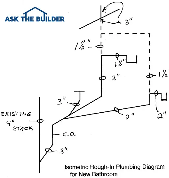
But, in this instance, Revit does not do a great job. If all you want to do is make 3D models of piping systems, the behavior described above is not important. However, many, if not all states, require the submission of approval drawings to get a plumbing permit. Those drawings have to clearly distinguish waste piping from vent piping. In our state, we submit a plumbing plan, and a waste and vent isometric. The isometric drawing is key, because it is difficult to distinguish the two systems in plan view. By using filters, and designating piping as waste (sanitary) or vent, you can quickly generate an isometric view showing the waste piping with solid lines and the vent piping with dashed lines.
If you have to move a fixture, or change the piping, you can do so in a plan or section view, and the isometric will change automatically. So, it is frustrating to pull up the isometric when you think you are done, and find that all of the vent piping has changed to solid lines. You could duplicate some fitting families, change the connectors from 'fitting' to the proper system type, Link the two sanitary connectors and have the vent connector by itself.
This can get very complicated though. I had a similar situation with Domestic Hot Water, I had a Recirculating system and had to create a 'Special' Tee to separate it from the system and get the calcs to work. For that reason, I utilize 'Pipe Types' to separate Waste from Vent and create a filter to display them differently.
I cannot use the sizing calcs, but that gets done manually here anyway. The blog post focus is on the fixture units calculating properly but it's really all the same problem, sanitary and vent system documentation/behavior. The solution for now is to break the two systems so they don't interfere with each other. As describe in the blog post, putting a cap between the sanitary and vent pipe sections doesn't really harm the model and allows the fixture count (and pipe appearance) to maintain their own integrity. No, Autodesk has not resolved the issue yet, as of Revit 2015. Alfredo wrote a reply to (at RevitForum) about a carrier family which might offer another solution.
I don't recall whether the family manages to propagate the fixture units properly when vent pipe is connected or what my post describes is necessary. It is not ideal, but the only way I have been able to succesfully keep my piping in order 'graphically' is through the use of worksets. I have a workset for sanitary, vent, storm, domestic water, plumbing equipment (fixtures, drains, etc.), natural gas, and others on a project by project basis. I then created filters for the vent and plumbing equipment worksets that I use to control the visibility of the pipes / fixtures.
This is not ideal, as my vent piping is technically on the sanitary system, but it allows me to create drawings that look nice. You could say that I use worksets in a similar way as one would use layers in AutoCAD.
I also do my calculations outside of Revit, so I am not sure what kind of impact this has on Revit's calculation features. I hope this is a helpful work around. Download Windows 10 Free Full Version.
It seems to me that the best way to work with Revit is to work around it. My two cents: Unless you are using Revit for sanitary vent pipe sizing (I doubt anyone does), I see no reason at all to use a separate vent system for the vent piping. I set my projects up with a sanitary vent pipe type, which I use for all vent piping in the sanitary system. I also use a template that includes one simple filter that applies the typical dashed line type to the vent pipe type. So other than just using my san-vent pipe type when modeling my sanitary system, it's just a quick application of the template to my sanitary views. This setup does require modifying a pipe tag for the vent piping that references the pipe type as opposed to the piping system abbreviation.
This setup has worked great for me. I doubt Revit will ever be used to size sanitary vent piping. The fact that the venting method used in your sanitary branch or fixture layout will have greater influence over the size of the vent, not the drainage fixture unit count, Revit still has a long way to go before real sanitary vent sizing is available. I ususally draw the sanitary pipe from the trap and elbow down to start the stack. Then click the '+' sign on the elblow to create a sanitary tee and draw that up the ceiling. Then from a 3D view, I click vent pipe from the sanitary tee and drag it up vertically a little bit to create a space and then change the system type to vent from sanitary. Then I drag and connect back to the sanitary tee, and it doesn't affect the sanitary system.
This has worked well for me, and with the added feature of 'divide system', I rarely cause a global headache. Another method I have used works well if you don't use plumbing fixtures in the MEP model, and just reference those from the architectural link. I would have plumbing fixture families for all fixture types, but they would be very simple with minimal graphics, and only have sanitary, vent, and trap connections. I would copy these around at all of my fixture locations, and they would already have the correct size, fixture units, and systems ready to go. Both these methods work well with copying the assemblies around to save time.
I thought about saving these assemblies as 'groups' in revit, but the systems tend to go 'undefined' once the group is loaded. Hi, This problem affects other services, too. HVAC pipework with Bypasses, for example. The fix is simple: change the connectors' Classification in the Family editor. Classifications have 3 settings that are not named after a specific service: Global, Fitting and Other. If you right click the fitting you're using and edit the family, you'll notice that all the connector classifications are set to 'Fitting'. Change the middle one to 'Vent' and the others to 'Global', save it as new family with a suitably obvious name and load it in.
You won't need that many 'special' fittings and it takes moments. TBH, although it works perfectly for me, I don't truly understand the differences between Global, Fitting and Other, I just try different things until it works. A problem with existing fittings getting redefined this way is they seem to have a habit of holding on to their old ways.
You have to Tab-select until you can select the System, delete it (which makes the system 'undefined'), and then add a scrap piece of pipe with the system you want. Sometimes you have to delete multiple systems in this way. Eventually it works! Bill Evans Transcriptions Pdf Free. I should point out that I don't produce anything in Revit for any kind of engineering Analysis; all my pipes systems are joined up but I only really do all this to make my Annotation Tags display the right Systems. I'm only interested in spatial coordination and Installation drawings.
This isn't a reply, but a continuation of my original post. In answer to one post, NO, Autodesk has not made a comment that I am aware of. I opened the generic coupling family, saved it as a 'separator coupling'. Both connector elements were set to FITTING. I changed one to SANITARY, and the other to VENT.
If I place the separator coupling at the end of a sanitary pipe, I can then pick the other end and select DRAW PIPE to draw the vent pipe. I can change the sanitary section to vent and back, and the vent section is not affected. When I attach the separator coupling to the end of a sanitary line, it appears that Revit orients it correctly. However, if you insert it into a sanitary line, the results are uncertain. Notice that the FITTING connector type allows the system type to propagate through the fitting--the fitting assumes the system type of the pipe connected to it. The separator coupling doesn't have this flexibility. If I connect pipe to both sides, and then change one of them to, say, Hydronic Supply, the pipe disappears.
BTW, changing both connectors to GLOBAL doesn't work. The system type will be the same on both sides. Needless to say, my separator coupling only works with VENT to SANITARY connections. I will have to create another coupling to connect a BYPASS line, for example, into a SUPPLY/RETURN network. Now, on to another topic--Mechanical Equipment. Revit still insists on lumping HVAC equipment and Plumbing equipment together. Now, if Revit did offer separate categories for HVAC and plumbing equipment, I would also want a Process equipment type, and so on.
I set up a MECHANICAL EQUIPMENT TYPE project parameter that I can use to identify a piece of equipment as HVAC, PLUMBING or anything else. Then I use filters to hide or show the type I select for a view.
This approach works, but it seems that Autodesk should be able to come up with a more elegant solution. Another topic: Revit allows you to connect one pipe to another with a TEE or a TAP. That's fine for most piping systems, but it's not enough for sanitary waste lines. You frequently need to connect one waste line to another with a WYE, or a combination WYe & 1/8th BEND. Yes, if you start far enough away from the line and draw the branch at a 45 degree angle, Revit will make the connection with a WYE fitting--SOMETIMES. At other times, it draws a fitting that I have never seen it a fitting catalog. Actually, I believe it's trying to draw a WYE, but since it apparently can't determine the flow direction, it draws it facing the wrong way and makes a 135 degree connection instead of a 45 degree connection.
BTW, why can't Revit determine the flow direction when the line already contains tees or wyes that are properly oriented? I didn't make it clear in my previous post that it's the T-fittings I'm modifying, not the Couplers/Union pieces. Couplers have a habit of disappearing if you edit the pipe in some ways. So I have a 4' rising stack, branch off to the side so it creates a Tee-piece, then I change the T-piece to my Custom Tee with 'vent' as the middle connector class. With the fittings I use, you can change the branch angle to say 45 degrees by pulling the branch pipe up in an elevation view. I have a few customised Valves also that I use for Flow/Return bypasses. Re: Wyes - If you join two pipes at 45degrees, what happens when you click the little '+' sign on the elbow?
Re: Mech / Plumbing Equipment: Isn't it all 'mechanical' equipment, as in, it has moving parts? A pump on a drainage system is still Mechanical and you might get the same pump used for other services.
A motor driven valve would be a Pipe Accessory.
I have used B31.3 for design of Ro desalination plants as the pressures involved exceed the AWWA and other water industry standarfds. There is absolutely no reason why ASME B31.3 cannot be used for the water industry.
The design, fabrication inspection and testing will produce a piping facility you can depend upon. Certainly any austenitic, duplex or super duplex piping will be well covered. It can also be used for GRP with a material guide such as ISO 14692 rather than the out of date BS 7159 or the water industry AWWA M45. Many water and waste water industry plants have dangerous chemicals and use of B31.3 is suitable.
RE: Designing a Water / Wastewater Treatment Plant to ASME B31.3 (Chemical) 9 Dec 08 02:01. KenA, that is exactly the situation we have here, the water treatment plant is part of a larger facility that is being designed to B31.3. It does indeed add cost and time. All chemical feed systems to the water treatment process will be designed to B31.3. But this is small diameter (less than 2'), low pressure, low temp piping. No thermal movements expected. Short pipe runs and pretty straightforward piping system.
The 'problem' becomes designing the 20' and greater, flanged DI to B31.3. That is just not common / done at municipal water and wastewater treatment plants for the most part - for several reasons. The burden of providing pipe supports is often left to the contractor in those types of municipal design-bid-build projects, and is often covered somewhat vaguely in an interior process piping specification (a spec may reference MSS standards for supports). These are pretty straight runs, the building is ~100' x 100'. Pipe is layed out in AutoCAD, not in AutoPipe, ceasar or these other analysis systems. Is there any way to provide a simple, cose effective B31.3 analysis on this pipe that does not significantly impact schedule?
RE: Designing a Water / Wastewater Treatment Plant to ASME B31.3 (Civil/Environmental) 10 Dec 08 08:37. I do not know of any AWWA standard that is directly related to B31.3. That said, I am also not familiar with B31.3.
I would suggest contacting the Ductile Iron Pipe Research Association () and see if any correlation exists between the ANSI B31.3 and applicable AWWA/ANSI/ASTM standards for ductile iron pipe may be substituted in lieu of B31.3. If so, then DIPRA has a set of computer programs (which are free) for the design of ductile iron pipe which may be useful. RE: Designing a Water / Wastewater Treatment Plant to ASME B31.3. What you should be referencing is an in-house piping standard. Guidance supplementing piping standards is necessary because the various codes provide no explicit rules for functional design, material compatibility with fluid and environment (erosion/corrosion protection, radiation effects, etc.), layout, serviceability, steam tracing, grounding, valve and component selections, design of pipe supports, material traceability, gasket selection, as-built tolerances, insulation, cleaning for special process, etc. For certain services some options available through piping codes must be excluded, made more stringent, or supplemented by the designer.
Larger CPI and HPI corporations have in-house piping standards that guide the design of piping systems. If you do not have access to any corporate standards, I would build on the standards that were developed by other firms. It would be wise to read through a few of these standards for design inputs. Have are a couple of references: US Army Engineering and Design - Liquid Process Piping RE: Designing a Water / Wastewater Treatment Plant to ASME B31.3 (Mechanical) 11 Dec 08 20:37. Owners of water and wastewater plants at least in municipalities with long history have for many decades had access to, and in many cases at least some direct experience with, many different choices for piping materials, including all those mentioned on this thread. I believe (based on looking at a lot of plans and specifications for many decades) that a major if not THE major choice at least in most fluid handling lines (and particularly for the very largest/in many cases oldest municipal plants/users with longest experience) is ductile iron piping.
I suspect there is a whole lot that has been considered in this useage. While of course Engineers certainly have a right (and daresay responsibility) to specify/design whatever piping system in their experience/opinion/analyses will do the best job, and not saying whatever pipe material will not work for any particular treatment application, different piping materials are not equal in many respects including successful performance history. Care should be applied and maybe particularly in making changes to known and long-term successful practice. Perceptions and whatever code or piping standard one thinks should be applied do not necessarily change these realities. What I am confused about is the 'need' to do stress analysis on a pipe he said will not see any thermal fluctuations. As an owner, (or a design firm making recommendations to owners) you can set-up 'practices' in your specs as to when stress analysis is required. If you know you have no 'real' stresses other than loading, (which you have span rules to accomodate) you shouldn't need to run Ceasar.
(If you have good piping design with flexibility allowed). RE: Designing a Water / Wastewater Treatment Plant to ASME B31.3 (Chemical) 31 Dec 08 11:03. Just stumbled upon this thread, and maybe a bit late to provide any value, but stress analysis for water and WW is typically limited to the issue of 'warm', empty pipe heated in the sun, or 'cold' empty pipe exposed to. Plenty of 316L austenitic stainles steel used in water and watewater plants. Refer for some very good technical papers on the subject. With tight programs it is certainly more flexible to use than flanged ductile iron.
The agian many lants use ABS, PP, PVC GRP these days as they are certainly cost effective against the legacy materials. For large sizes PE or epoxy coated steel has proved to be a useful material. RE: Designing a Water / Wastewater Treatment Plant to ASME B31.3 (Civil/Environmental) 28 Jan 09 09:21.
While there is no doubt the utility of the material in some fields and applications, and it is also apparently true as stanier states that stainless steel has seen some increasing treatment plant use, particularly in last few years and e.g. And in some European areas etc.
I noticed recently however that after generally only a few years of use some issues have developed in plants, and even with some 316L etc., and it is e.g. The subject of a Danish research program that was summarized at that makes an interesting read (I don't know if this paper and other third-party papers I have seen is on the site stanier refers to).
RE: Designing a Water / Wastewater Treatment Plant to ASME B31.3 (Mechanical) 28 Jan 09 17:22. Thanks rconner for the link. Many plants in Australia & SE Asia have been using spiral wound stainless steel for over twenty years. The success comes from doing properly. Engineering the thin wall stainless steel so that there are reinforcing pads at branches.
Doubling plates to prevent local buckling stresses at pipe supports. That is using qualified weld procedures, qualified welders, pickling and passivation. Hence if you are gong to use ss in these plants ASME b31.3 is a good choice to ensure that the design, fabrication, testing, installation and operation will succeed. Others will claim that this is level of engineeering is unnecessary for ductile iron piping.
Years of seeing design by cataogue for DI is testimony to the fact that it can be done. Hence ss will cost more in engineering but generally less in supply/erect than ductile iron.
DI is generally remanufactured from scrap ferrous products. The price vaaries with supply. Ss depends on the price of nickel, which has just nose dived. It depends on where you are in the world as to the overall cost. Myself I prefer ss as I have control over the engineering, particulalry in this litigous society.
RE: Designing a Water / Wastewater Treatment Plant to ASME B31.3 (Mechanical) 28 Jan 09 18:39.